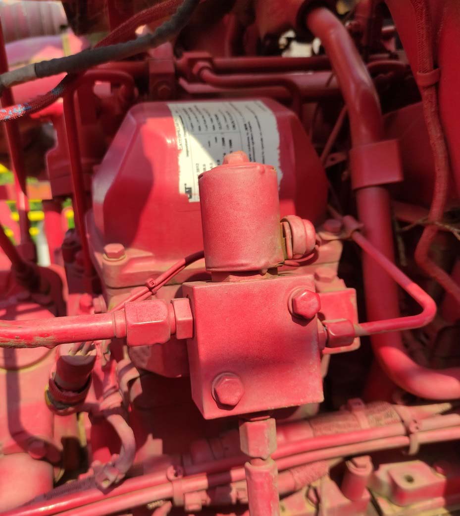
Air Shutoff System
Use this procedure to troubleshoot the electrical system if a problem is suspected (active or easily repeated) with the Air Shutoff system.
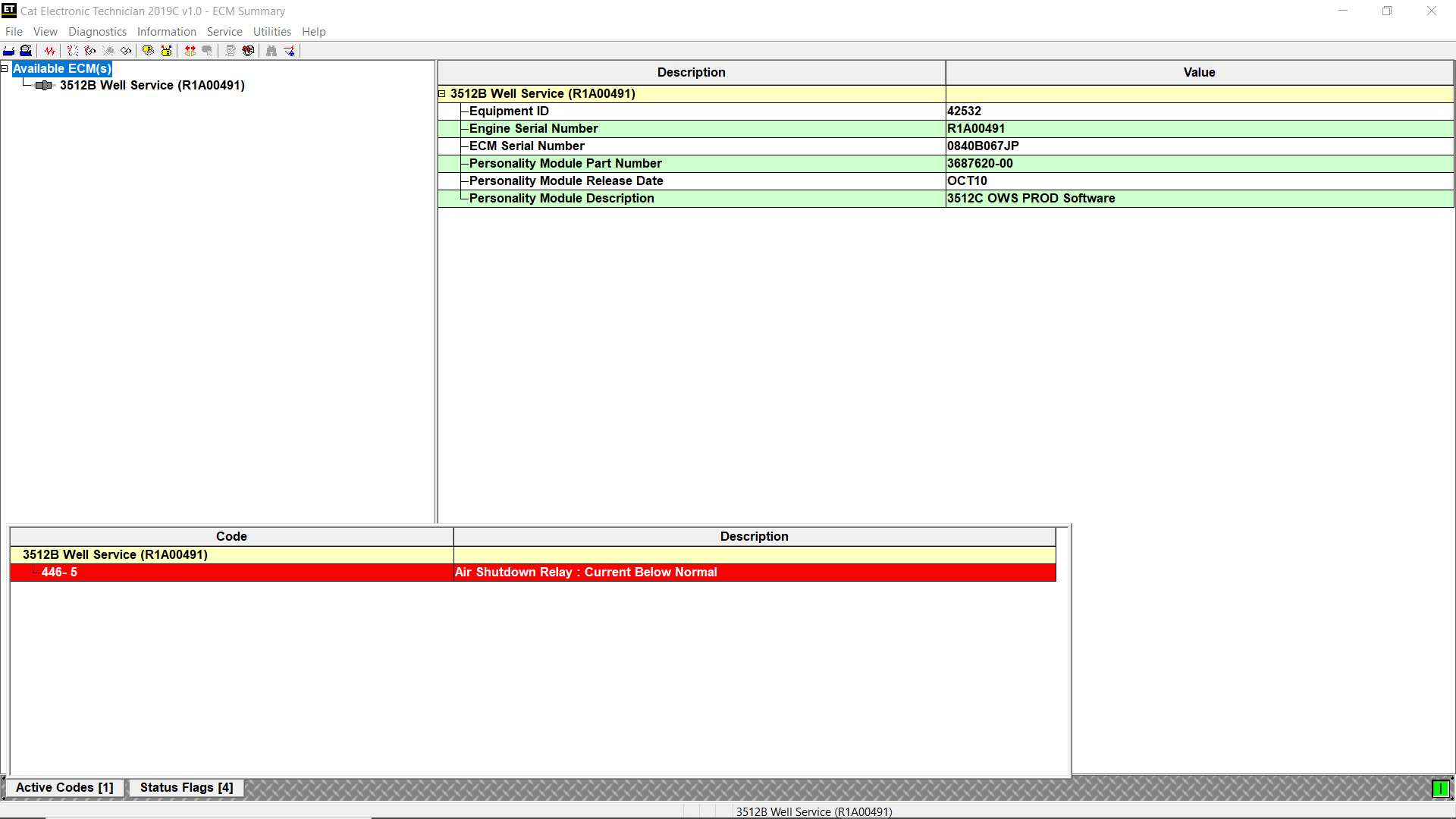
* (446-5) Air Shutdown Relay current below normal – The Electronic Control Module (ECM) detects an open circuit and/or a short to the +Battery in the solenoid circuit.
* (446-6) Air Shutoff Relay short – The ECM detects a short circuit to ground in the solenoid circuit.
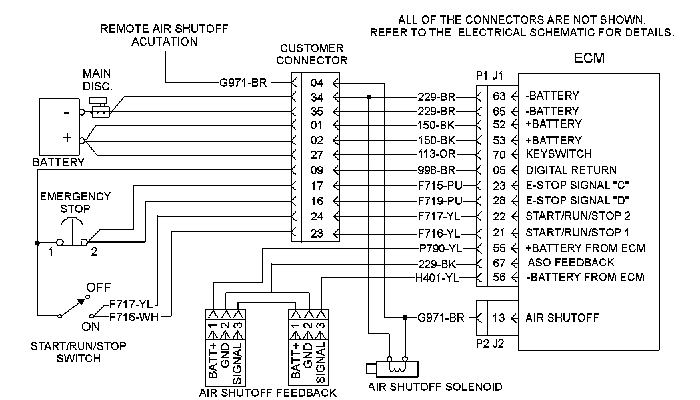
The ECM can stop the Engine by shutting off the air supply in an emergency situation. The ECM activates the Air Shutoff Solenoid which activates the Air Inlet Shutoff valve.
The first condition occurs when the Operator initiates an emergency shutdown. When the shutdown is
recognized, fuel is shut off and the Air Shutoff Solenoid is activated. The second condition is for an Engine overspeed. Read More: How to Setting or Testing the Engine Overspeed using Caterpillar ET Software?
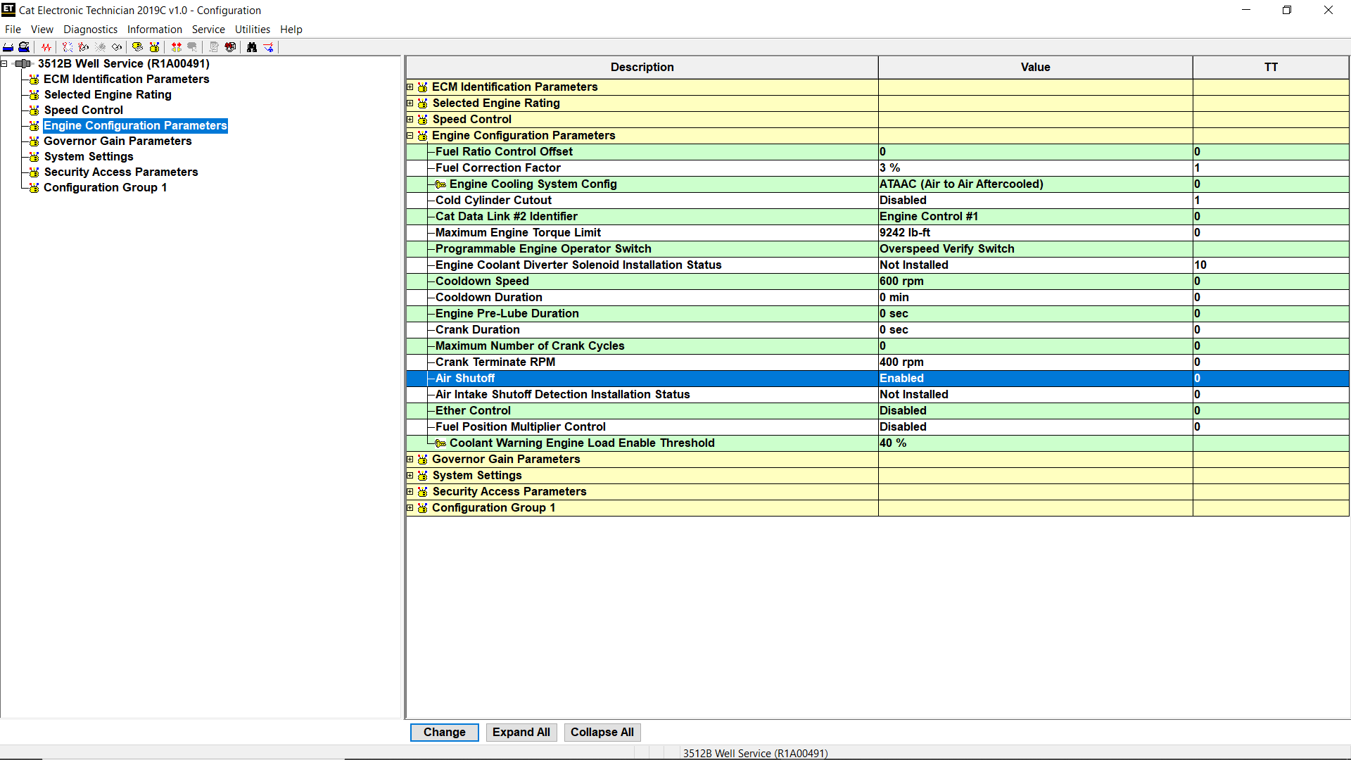
Regardless of the reason for activation, the main power to the ECM must be turned OFF for 3 seconds in order to reset. Note: The Air Shutoff is optional. A programmable parameter must be set with Cat ET in order to enable the Air Shutoff (Configuration Tool).
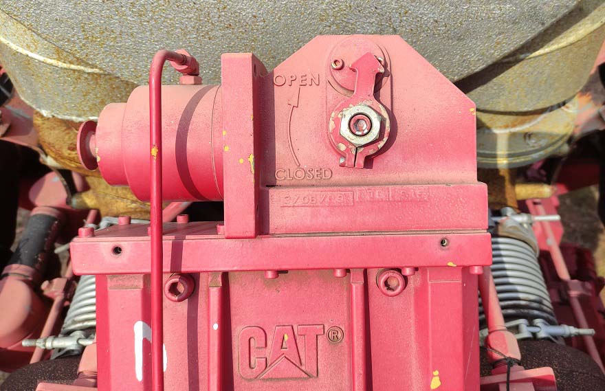
The switch at the Air Shutoff valve allows the ECM to determine if the Air Shutoff valve is open or closed. If the shutoff valve is closed, the switch is in the closed position and the ECM will not start the Engine. Open the Air Shutoff valve in order to start the Engine. Note: Ensure that the Air Shutoffs are manually reset after an emergency stop in order to start the Engine again.
Test Step 1. Inspect Electrical Connectors and Wiring
A. Remove power from the ECM.
B. Thoroughly inspect the J1/P1 ECM connector and the J2/P2 ECM connector. Inspect all of the
connectors that are associated with the circuit.
C. Perform a 45 N (10 lb) pull test on each of the wires in the ECM connectors that are associated with the circuit.
D. Check the ECM connector (allen head screw) for the proper torque.
E. Check the harness and wiring for abrasion and for pinch points from the sensors back to the ECM.
Expected Result: All connectors, pins, and sockets are coupled and/or inserted and the harness and wiring are free of corrosion, of abrasion and of pinch points.
Test Step 2. Check for Active Diagnostic Codes
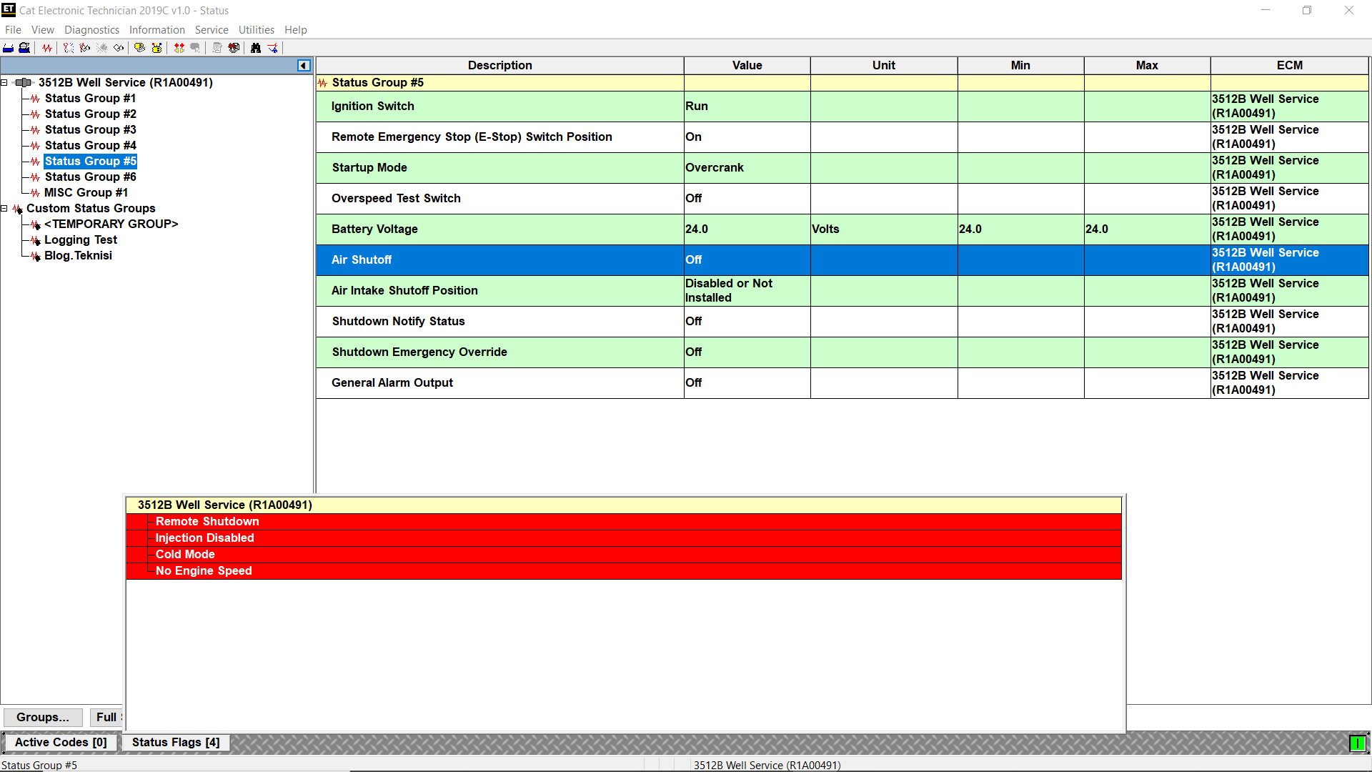
A. Connect Cat ET to the service tool connector. Read More: How to Connecting Caterpillar ET Software to the ECM.
B. Monitor the active Diagnostic code screen on Cat ET. Check the Air Shutoff system for an active
Diagnostic code.
C. Activate the override for the Air Shutoff system. Monitor the active Diagnostic code screen on Cat ET. Check the Air Shutoff system for an active Diagnostic code.
Expected Result: No Diagnostic codes are active.
Test Step 3. Create an Open at the Connector for the Air Shutoff Solenoid
A. Disconnect the connector for the Air Shutoff Solenoid.
B. Monitor the active Diagnostic code screen on Cat ET. Check for an active Diagnostic code for the Air
Shutoff system.
C. Activate the override for the Air Shutoff system. Monitor the active Diagnostic code screen on Cat ET. Check the Air Shutoff system for an active Diagnostic code.
Expected Result: A 446-5 Diagnostic code is active when the solenoid is removed from the circuit (as Figure 1.2 above). The Engine harness and the ECM are OK.
Test Step 4. Create a Short at the Connector for the Air Shutoff Solenoid
A. Disconnect the connector for the air shutoff solenoid.
B. Install a jumper wire between the terminals of the connector for the Air Shutoff Solenoid.
C. Monitor the active Diagnostic code screen on Cat ET. Check for an active Diagnostic code for the Air
Shutoff system.
D. Activate the override for the Air Shutoff system. Monitor the active Diagnostic code screen on Cat ET. Check the Air Shutoff system for an active Diagnostic code.
Expected Result: 446-6 Diagnostic code is now active for the Air Shutoff system. The Engine harness and the ECM are OK.
Test Step 5. Test the Operation of the ECM
A. Fabricate jumper wires that can be used to replace the wires in the ECM connector for the Air Shutoff Solenoid. Crimp a connector socket to one end of the jumper wires.
B. Disconnect the appropriate ECM connectors for the Air Shutoff Solenoid.
C. Remove the wires for the Air Shutoff Solenoid from the ECM connector.
D. Install the jumper wires into the terminal locations for the Air Shutoff Solenoid at the ECM connector.
E. Connect the ECM connectors.
F. Check the operation of the ECM by creating an open and short at the ECM.
Expected Result: 446-5 Diagnostic code is active when the wires from the Air Shutoff Solenoid are open at the ECM connector. 446-6 Diagnostic code is active if the wires from the Air Shutoff Solenoid are shorted at the ECM connector.
More information about Heavy Duty Truck diagnostic Scanner , please refer to https://www.obd2tool.com


Leave a Reply