
This instruction show you guide on how to fault trace wires and connectorsin general.Detailed fault tracing instructions for special failure are described in Volvo Tech Tool.
Preparations:
Volvo Premium Tech Tool PTT 2.8.0 FULL Development With New ACPI Plus for Volvo Diagnostic
Visual checks
Check that the wires are correctly clamped and secured.
Wires clamped too tightly can cause poor contact or an open circuit.
Avoid bending the wire harness and fastening it too tight on the housing/contact.
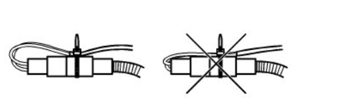

Make sure the lines are not too tightly clamped.
Hard clamped wires can cause bad contact or open circuit.
Volvo-Trucks-Wires-and-Connectors-Fault-Trace-Guide-2
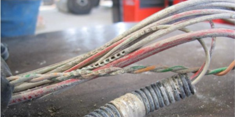
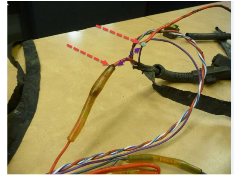
Check that the cables do not have damage from rubbing. Look specifically at places where the harness is near frame edges and consoles.
Volvo-Trucks-Wires-and-Connectors-Fault-Trace-Guide-3
The reason for chafing damage can be:
A missing clamp
A loose clamp
Improper clamping (too long, too tight, stretched)
Connectors check
Oxidation affects the resistance of a contact which can cause permanent or intermittent interruption in the electrical circuit.
Note: Water intrusion with discolorations in Control unit connectors requires replacement of the control module
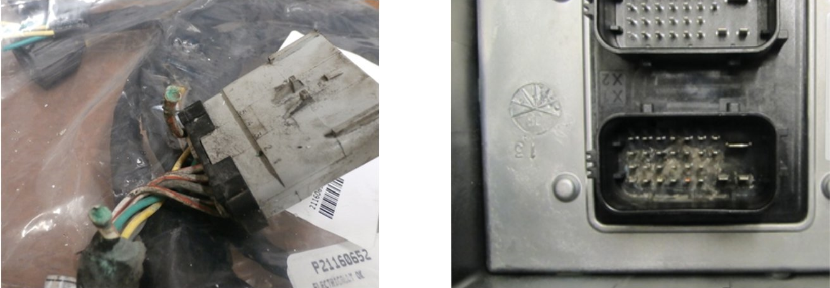
Damaged or incorrectly installed terminals
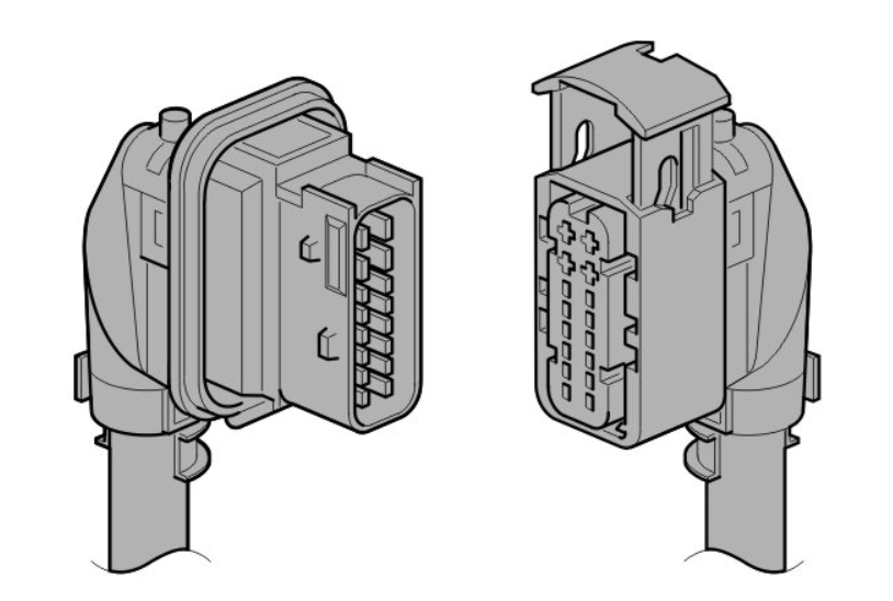
Check that the terminals are properly locked and cannot be dislodged
Check that the terminals are not bent or broken
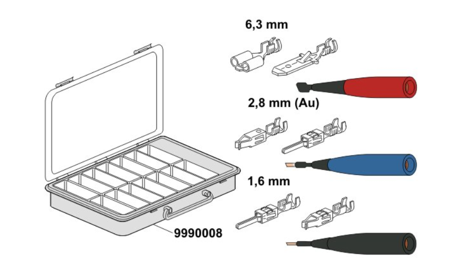
To control the elasticity of the terminals and if the terminals are locked in the connector, use the required test pins to avoid damaging the terminals.

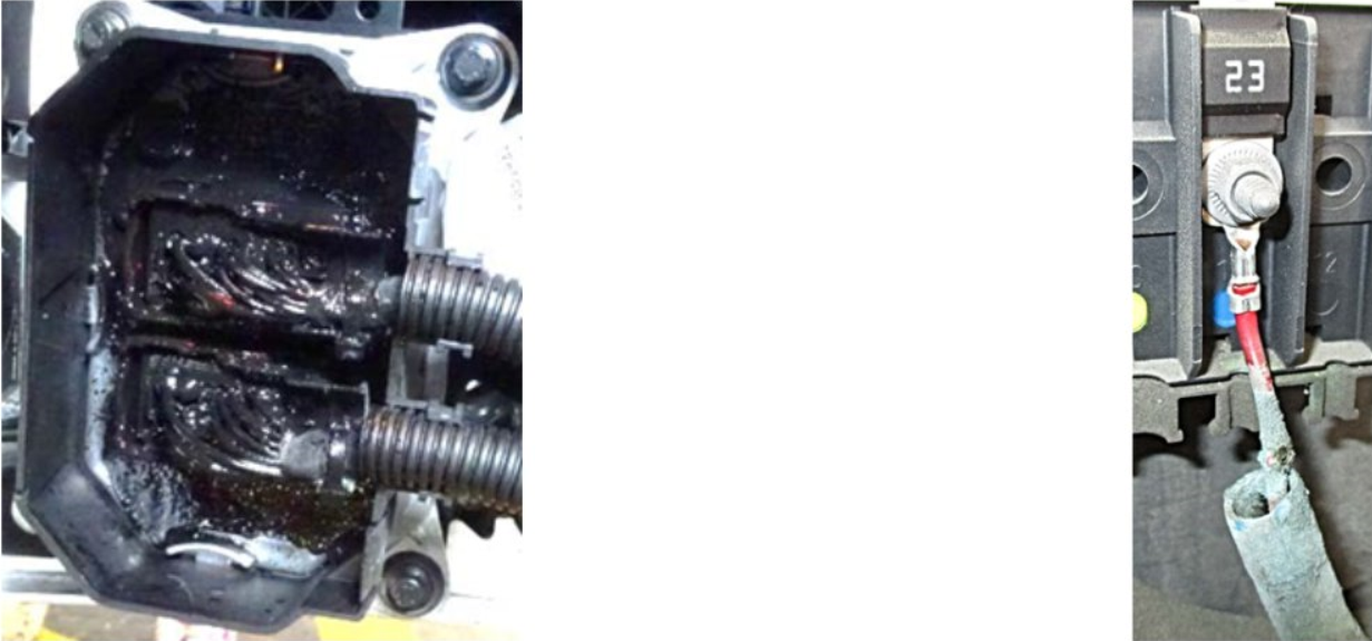
Ground connections may look good but can be corroded and/or loose which will give a poor ground connection.
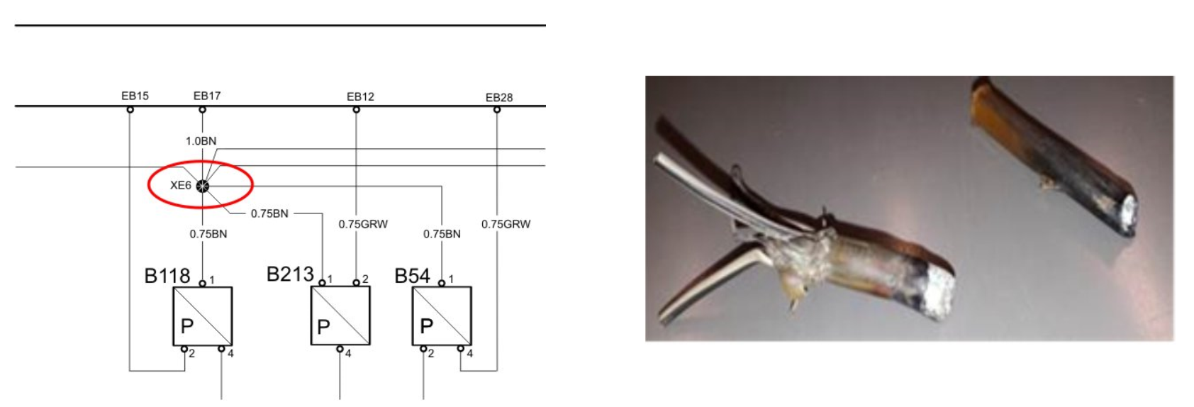
Wire splices
For chassis harnesses, corrosion in splices and where the wires connect to a splice is common. Also in common areas where the wire is connected by a y- manifold and the wire harness is not taped.
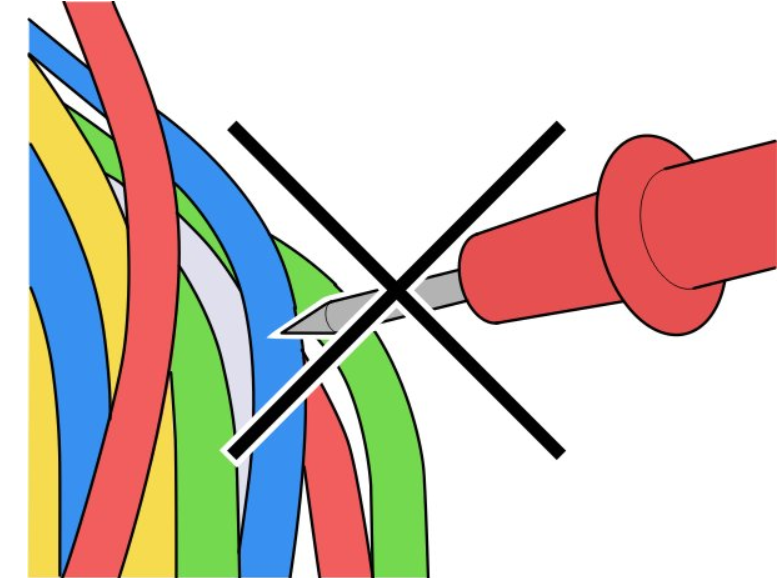
Electrical measurements
Considerations:
Never measure by piercing through the insulation and moisture seals in wires and connectors.
Measure a wiring harness using a multimeter and use appropriate measuring cable and measuring box.
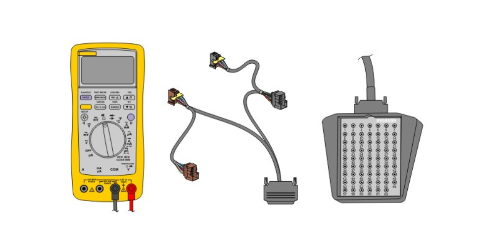
Note: When a test cable is not present, use test pins.
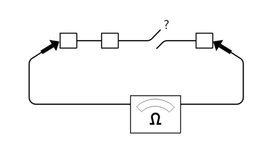
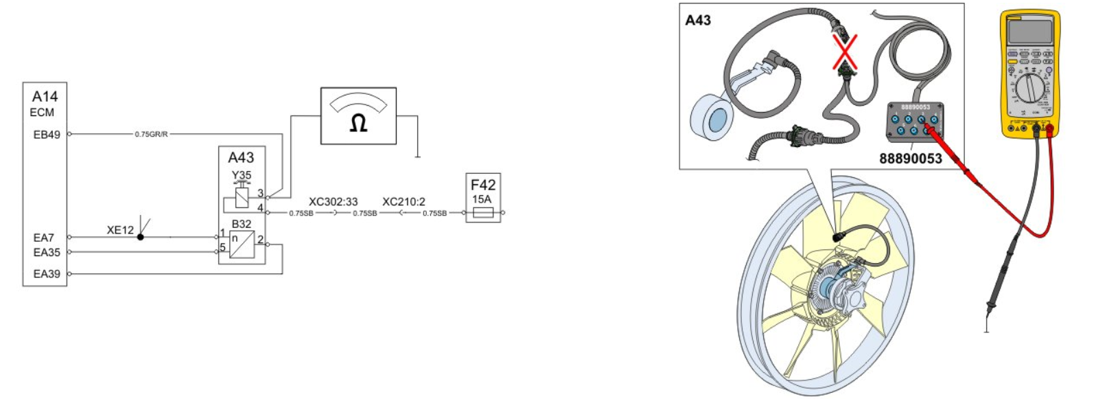
Open Circuit
Checks:
Disconnect the connectors at both ends of the wiring harness.
Measure the resistance from each end of the wiring harness.
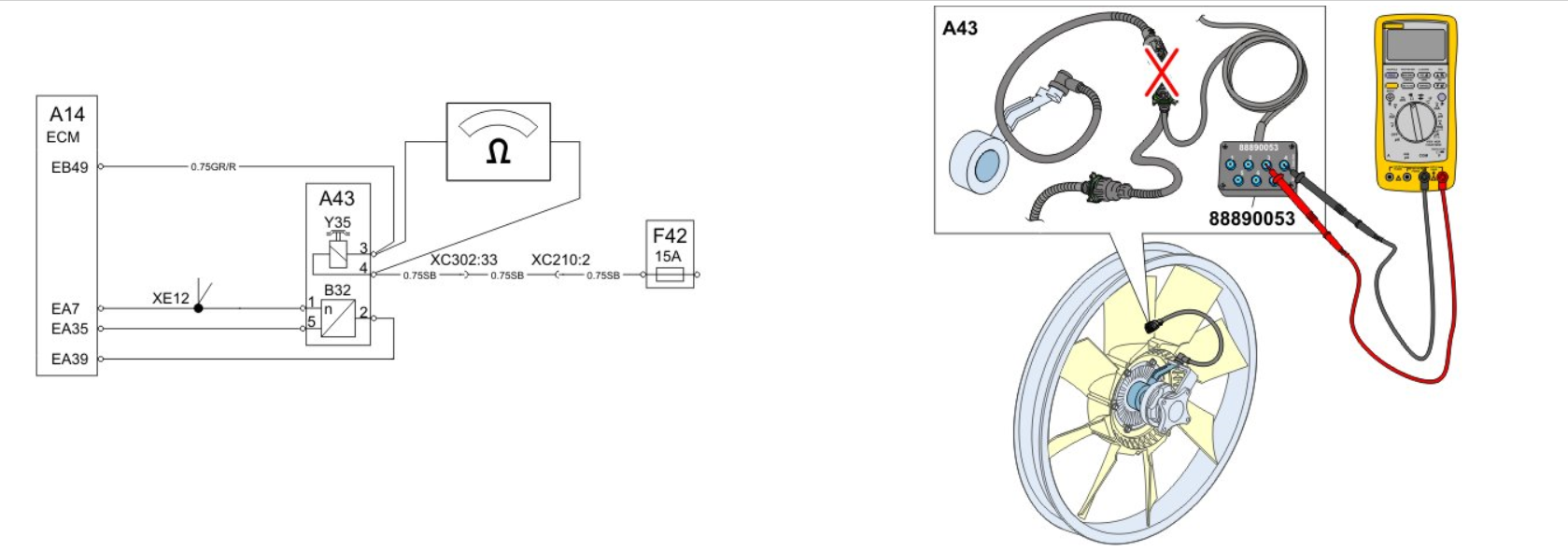
Short Circuit
Checks:
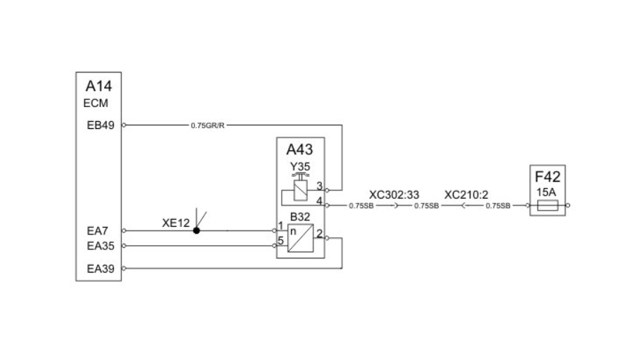
Splices in the wiring harness (XE12) affect the measurements so it is important to disconnect affected connectors to all components in the circuit. For example, it can be good to narrow the fault tracing in the engine wiring harness by disconnecting the engine interface connector from the chassis harness.
Measurement 1: check for short circuit to ground.
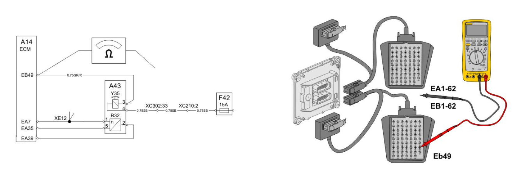
Measurement 2: check for short circuit to voltage.
Measurement 2: check for short circuit to voltage.

Cleaning connectors and terminals
– Only clean by using workshop air pressure.
– Only clean by using workshop air pressure.
Caution
If there is moisture in the connector to a control unit do not use workshop air pressure because these connectors are not moisture-proof. If the control unit function is intact it’s better to let it dry by itself if there is no discoloration in the connector. Using compressed air poses a risk that the moisture being pushed into the control unit and leading to damage inside.
Note: Blowing too hard can cause connector seals to blow out. Do not use workshop air if it includes too much oil.
– Grease (PN 1161417) can be used in connectors to protect against moisture.
Note: Do not overfill with grease which can cause the connector seals to be pushed out.
No type of spray that contains silicone oil may be used in the connectors.
Target values
Target values may vary depending on the function of the electrical circuit. Some features are more sensitive to deviations than others. Therefore, it is important to follow the instructions and expected values in the fault tracing instructions when determining if there is an error or not.
Intermittent errors
Intermittent faults can be detected during measurement by wiggling wires and connectors.
If possible, you may want to do a test run and repeat the conditions described when the error occurred.
A multimeter can be used to detect a poor connection.
Set the multimeter to the appropriate setting
Connect the tools according to the information in the chosen data link schematics
After reading the values, press the MIN / MAX button
Wiggle the wires or perform a test drive while notifying the minimum and maximum values on the multimeter to find a bad contact.
Leave a Reply