The Multiple Diagnostic Interface 2 (GM MDI 2) User Guide provides a quick reference and overview of the Multiple Diagnostic Interface 2 system.
Everything contained in this manual is based on the latest production information available at the time of publication. The right is reserved to make changes at any time without notice. No part of this publication may be reproduced, stored in any retrieval system, or transmitted in any form by any means, including but not limited to electronic, mechanical, photocopying, recording, or otherwise, without the prior written permission of GM Customer Care and Aftersales. This includes all text tables, illustrations and charts.
1. WiFi Compliance
This equipment complies with the following worldwide wireless standards.

2. Safety / Environmental Compliance
This equipment complies with the following worldwide safety and environmental standards.

3.Product Description
Overview
The Multiple Diagnostic Interface 2 (MDI 2) is used by professional technicians as an aid in diagnosing and repairing automotive electrical and electronic systems. The MDI 2 is designed to connect the vehicle to a host PC computer application which then functions through the MDI 2 for data transfer and Electronic Control Unit (ECU) reprogramming.
Using the MDI Manager PC application software, you configure the MDI 2 to communicate with a host computer. The MDI 2 is capable of communicating over a USB cable, Ethernet cable, or wireless network (WLAN).
User group
The product may be used by skilled and instructed personnel only. Personnel scheduled to be trained, familiarized, instructed or to take part in a general training course may only work with the product under the supervision of an experienced person.
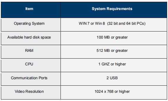
PC System Requirements
The MDI 2 Software runs on a PC/Laptop. The user interacts with the MDI 2 software for device setup, and configuration for SAE J2534 or ISO 22900 data transfer and ECU reprogramming. The following table lists the minimum PC/laptop requirements for installing and running the MDI
2 Software:
4. MDI 2 Kit Contents
The MDI 2 Kit includes hardware and cables needed to transfer data and reprogram ECUs on vehicles through the DLC connector.
The Wireless MDI 2 Kit (Bosch p/n EL-52100) US and Canada – Includes the MDI 2 assembly with two USB Wireless Adapters, DLC Cable, USB Cable, and Ethernet Cable. The Self Test Adapter is sold separately.
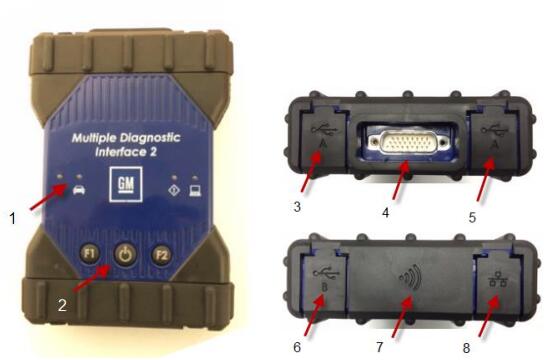
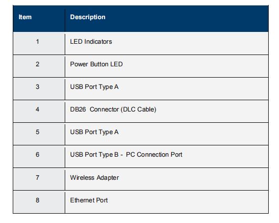
5. MDI 2 Connectors and Controls
A number of standard connectors and controls are available on the MDI 2 to facilitate operation and communication with vehicles and workshop networks. These connectors and controls are shown in the following illustrations.
6.Universal Serial Bus (USB – Item 6)
The MDI 2 has a fixed USB configuration which cannot be changed. This ensures that the MDI 2 can always be connected to a single PC running the MDI Manager software so you can configure LAN or WLAN settings required by your local network. In addition, it is important to note that a USB connection is recommended to configure and update the firmware on the MDI 2. USB connection must be made directly with the PC port. Do not connect through a USB hub.Ethernet
The Ethernet connection on the MDI 2 is set up and configured while the device is connected over USB to a PC running the MDI Manager software. It is possible to update the firmware on the MDI 2 using an Ethernet connection.
7. Wireless Local Area Network (WLAN)
The 802.11n WLAN connection on the MDI 2 is set up and configured while the device is connected over USB to a PC running the MDI Manager software.
MDI Manager Software
The MDI Manager software is a host computer application which runs on the Microsoft Windows operating system to configure and update MDI 2s. The MDI Manager software allows the configuration of MDI 2-to-host PC communications and facilitates MDI 2 firmware updates.
SAE J2534 Pass-Thru Support
The MDI 2 has been validated to work with General Motors PC based diagnostics and reprogramming applications.
The MDI 2 supports pass-thru programming of the flash calibration files that are stored in a vehicle onboard controller (e.g., PCM, ABS, VTD). Refer to specific operating instructions provided by General Motors. The MDI 2 design is based on the SAE J2534 Pass-Thru and ISO 22900 Modular Vehicle Interface standards, therefore the MDI 2 may also be compatible with vehicles built by other OEMS
8. MDI 2 Features
Data Link Connector Cable
The Data Link Connector Cable is the external test equipment (ETE) cable that connects the MDI 2 to the vehicle’s SAE J1962 Data Link Connector (DLC). The DLC Cable with the grey SAE 1962 connector is specifically designed for the MDI 2 and measures 1.8 meters in length.
9. Power Source
The MDI 2 is intended to be powered from the vehicle battery via the DLC Cable for normal use. If the MDI 2 does not have sufficient power (12V) to perform vehicle diagnostics, the MDI 2 will inform you of insufficient power for diagnostics by blinking the Vehicle LED in the color Red. This scenario can be seen when the MDI 2 is only
Leave a Reply