This section of Piwis Tester II describes how you can display the control units installed in the vehicle in a control unit overview by means of a control unit search.
The basis for this is an existing ODX project in which the control unit-specific data is stored. The system must check whether a control unit of the project is installed in the vehicle and what variant this is.
After a user action, the diagnostic application first performs a control unit search. The list of all or selected control units and their status is then shown in the control unit overview.
Action-specific buttons for this function group
Process with vehicle communication
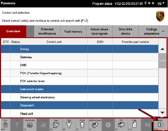
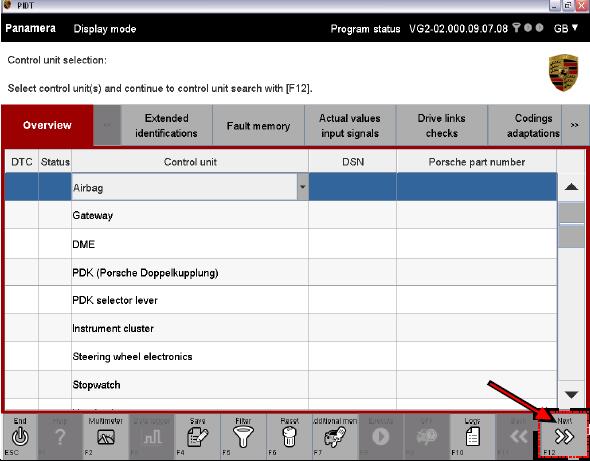
1. After the application has been started successfully, the list of control units for the respective ODX project is displayed in a control unit list.
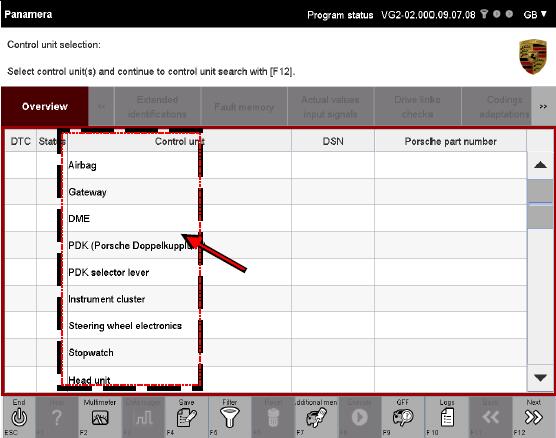
There are two possibilities for selection of control units:
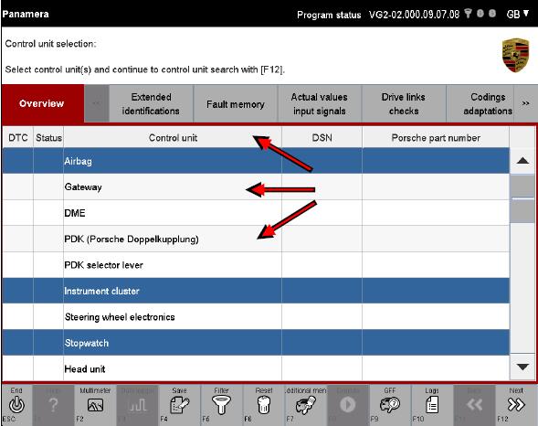
2. Select the desired control units by marking them. If you would like to deselect a selected control unit again, click again in the corresponding line.
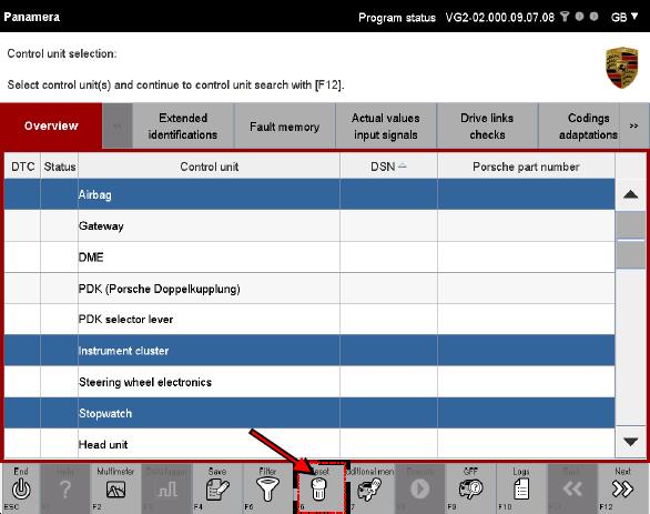
3. The complete selection can be cancelled again by pressing the <F6> button.
4. Then press the <F12> button to start the control unit search. The system now checks which control units or selected control units of the project can be addressed.
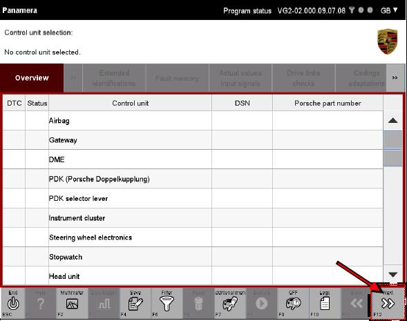
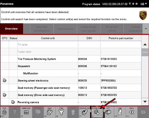
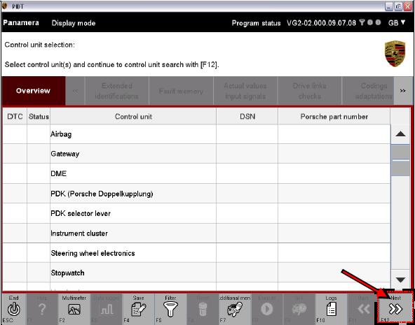
5. If you would like to perform a control unit search for all control units, press the <F12> without previously selecting a control unit. The Porsche PIWIS TESTER II system then checks which control units or selected control units of the project can be addressed.
Display of search results
The list of addressable control units is then displayed in the control unit overview. Depending on which selection variant you have selected, the list is displayed similarly to the list form shown in step 6 or step 7.
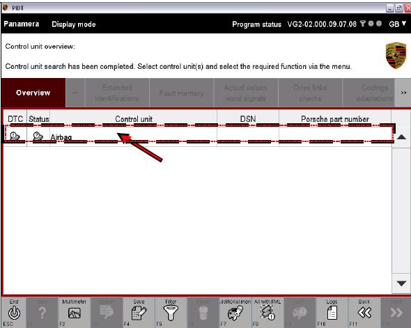
6. Display with previous selection (variant 1): Control units that were previously selected in the control unit list and are addressable are already preselected in the control unit overview.
7. Display without previous selection (variant 2): All addressable control units are displayed. The control units are not marked.
Note on display:
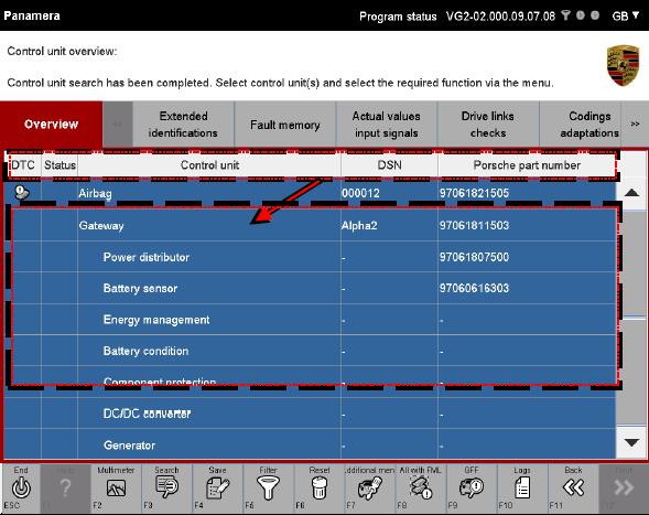
Control units for which no variant is detected are identified by a icon in the Status column. The data of the basic variant is displayed for control units that are labelled in this way. Control units that have a fault memory entry are identified by a ! icon in the DTC column.
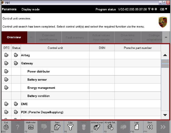
8. If it should not be possible to establish communication with a control unit, this is indicated by dashes in the list after the control unit name (A). These Professional Diagnostic Tool are greyed out and cannot be selected. Subcomponents of control units (so-called ECU-subcomponents) are shown indented below the respective control unit (B). You can work with these subcomponents in the same way as with the regular control units (also see additional information below).
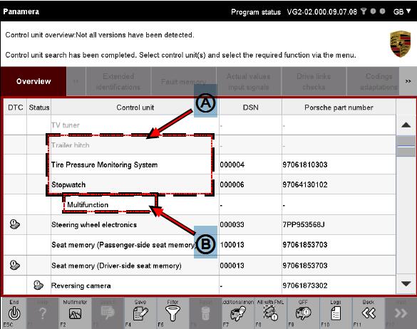
Note on display of subcomponents
If a higher-order control unit has subcomponents and you select a higher-order control unit and then change to a different function group or function, all subcomponents are implicitly selected as well. However, if you mark a subcomponent or several subcomponents and then change to another function group or function, any further action will be performed only for this selection.
Example:
You select the control unit Gateway and change to another function group. In addition to the main control unit Gateway, the following subcomponents are then also displayed in this function group:
Battery condition,Main fuse box, Intelligent battery sensor, Electric energy management (eEM) In contrast, if you have selected only the subcomponent Intelligent battery sensor and change to another function group, only this element is made available for a further action in this function group.
Next steps
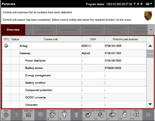
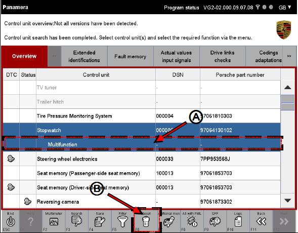
9. Now select the control units for which you would like further information from the list of control units. If you would like to deselect a selected control unit again, click in the corresponding line once more(A). The complete selection can be cancelled again by pressing the <F6> button (B).
Notes on selectability of function groups
* All function groups are available if you have selected at least one control unit or one subcomponent.
* No function group can be selected if you have not made an explicit selection.
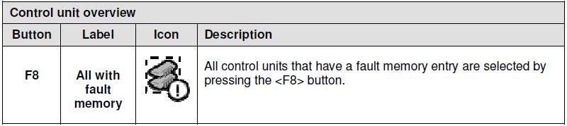
Notes on selectability of all control unit with fault memories
10. Press the <F8> button if you wish to select all control units that have a fault memory entry.
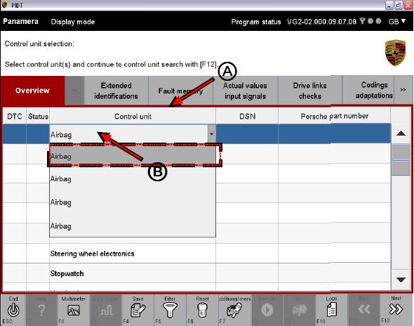
Process without vehicle communication (special procedure for View mode)
If diagnosis if performed in View mode, there is no communication with the vehicle via a VCI.
The variant detection process that normally takes place as part of the control unit search is
omitted as there is no vehicle communication.
In order to nevertheless access the data on the respective control unit variant, you must
select the variant in the control unit list. Proceed as follows:
1. Click in the Control unit (A) column for the respective control unit and select a control unit variant for each control unit via a drop-down menu (B). If you would like to have the basic variant displayed for the respective control unit, select the first/top entry in the drop-down menu. The complete selection can be cancelled again by pressing the <F6> button.
2. Then press the <F12> button.
3. All selected control unit variants or control unit basic variants are displayed.
4. Do not select a control unit if you would like to have the basic variant displayed for all control units. Then press the <F12> button.
5. The control unit basic variants are displayed.
6. The functions described in section 8.2 ff are then available, with the following restrictions:
Leave a Reply